SEPARATING WALLS (NEW BUILDINGS) SOUNDPROOFING


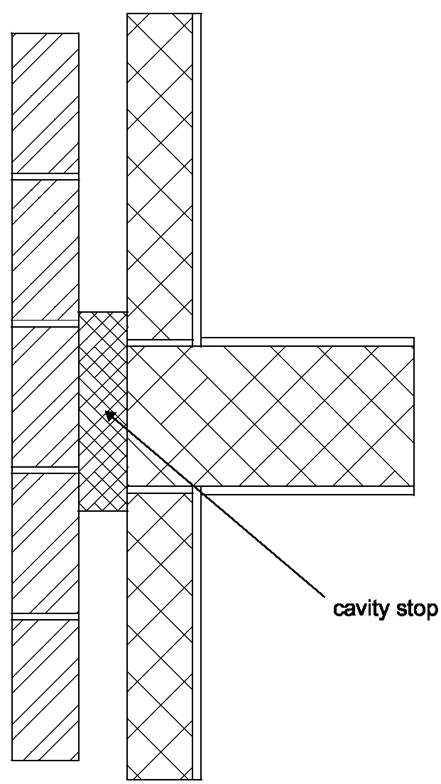
Diagram 2-5: Wall type 1 – external cavity wall with masonry inner leaf
Diagram 2-5: Wall type 1 – external cavity wall with masonry inner leaf soundproofing

Diagram 2-6: Wall type 1 – bonded junction – masonry inner leaf of external cavity wall with solid separating wall
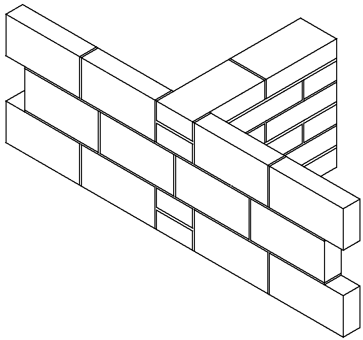
Diagram 2-6: Wall type 1 – bonded junction – masonry inner leaf of external cavity wall with solid separating wall soundproofing

Diagram 2-7: Wall type 1 – tied junction – external cavity wall with internal masonry wall
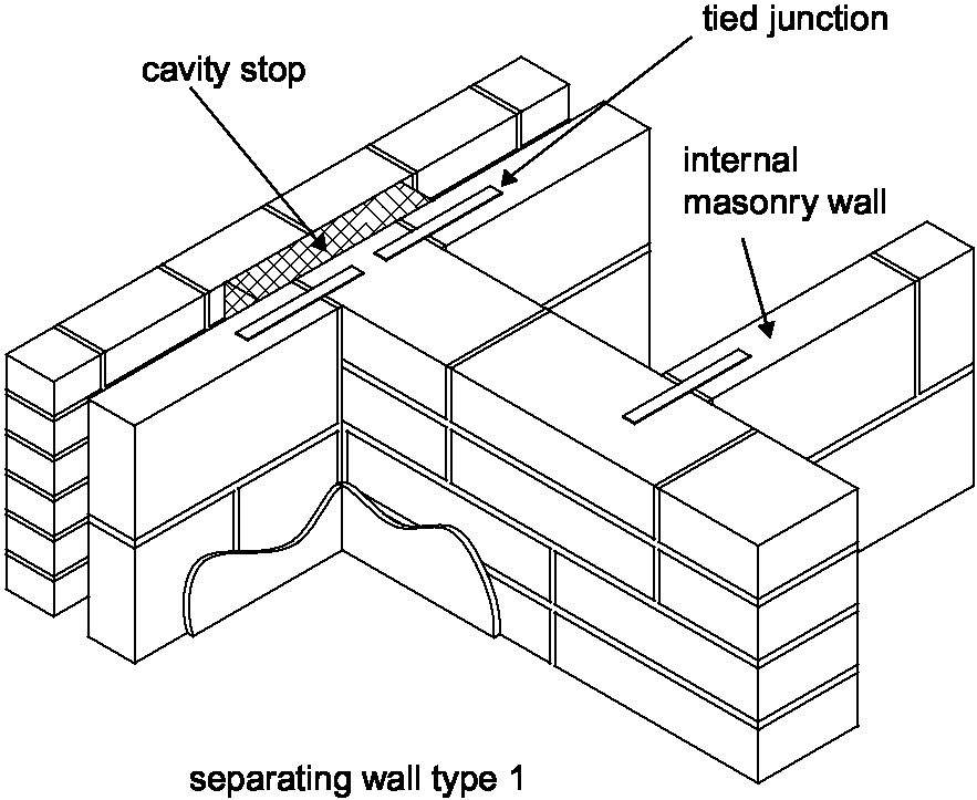
Diagram 2-7: Wall type 1 – tied junction – external cavity wall with internal masonry wall soundproofing

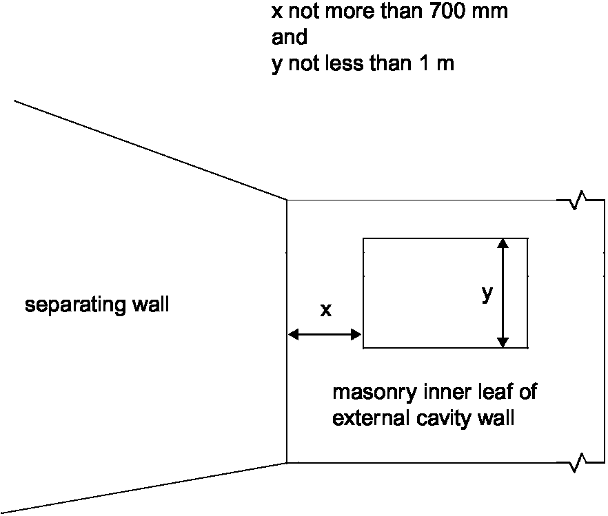
Diagram 2-8: Wall type 1 – position of openings in masonry inner leaf of external cavity wall
Diagram 2-8: Wall type 1 – position of openings in masonry inner leaf of external cavity wall soundproofing
Junctions with an external cavity wall with timber frame inner leaf

2.40 Where the external wall is a cavity wall:

  1. the outer leaf of the wall may be of any construction, and
  2. the cavity should be stopped with a flexible closer. See Diagram 2-9.

2.41 Where the inner leaf of an external cavity wall is of framed construction, the framed inner leaf should:

  1. abut the separating wall, and
  2. be tied to it with ties at no more than 300 mm centres vertically.

Resistance to the passage of sound 21

prev - Soundproofing For Document E compliance index - next