SEPARATING WALLS (NEW BUILDINGS) SOUNDPROOFING
Wall type 2: Cavity masonry
2.61 The resistance to airborne sound depends on the mass per unit area of the leaves and on the degree of isolation achieved. The isolation is affected by connections (such as wall ties and foundations) between the wall leaves and by the cavity width.
Constructions
2.62 Four wall type 2 constructions (types 2.1, 2.2, 2.3 and 2.4) are described in this guidance.
2.63 Two of these wall constructions (types 2.3 and 2.4) are only suitable when a step in elevation and/or a stagger in plan is incorporated at the separating wall.
2.64 Details of how junctions should be made to limit flanking transmission are also described in this guidance.
2.65 Points to watch
Do
- Do fill and seal all masonry joints with mortar.
- Do keep the cavity leaves separate below ground floor level.
- Do ensure that any external cavity wall is stopped with a flexible closer at the junction with the separating wall, unless the cavity is fully filled with mineral wool or expanded polystyrene beads (seek manufacturer’s advice for other suitable materials).
- Do control flanking transmission from walls and floors connected to the separating wall as described in the guidance on junctions.
- Do stagger the position of sockets on opposite sides of the separating wall.
- Do ensure that flue blocks will not adversely affect the sound insulation and that a suitable finish is used over the flue blocks (see BS 1289-1:1986 and seek manufacturer’s advice).
Do not
- Do not try and convert a cavity separating wall to a type 1 (solid masonry) separating wall by inserting mortar or concrete into the cavity between the two leaves.
- Do not change to a solid wall construction in the roof space as a rigid connection between the leaves will reduce wall performance.
- Do not build cavity walls off a continuous solid concrete slab floor.
- Do not use deep sockets and chases in the separating wall, do not place them back to back.
Wall ties in separating cavity masonry walls
2.66 The wall ties used to connect the leaves of a cavity masonry wall should be tie type A.
Cavity widths in separating cavity masonry walls
2.67 Recommended cavity widths are minimum values.
Blocks with voids
2.68 The guidance describes constructions that use blocks without voids. For blocks with voids, seek advice from the manufacturer.
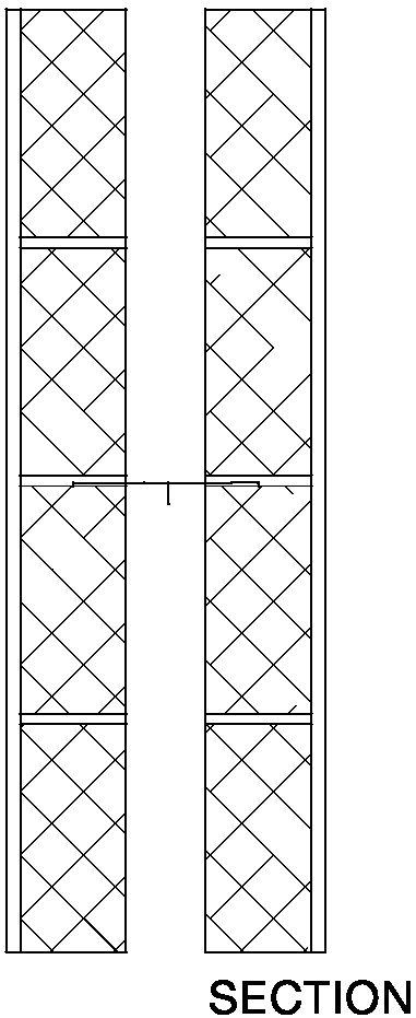
2.69 Wall type 2.1 Two leaves of dense aggregate concrete block with 50 mm cavity, plaster on both room faces (see Diagram 2-15)
- minimum mass per unit area including plaster 415 kg /m2
- minimum cavity width of 50 mm
- 13 mm plaster on both room faces
Example of wall type 2.1
The required mass per unit area would be achieved by using
- 100 mm block leaves
- block density 1990 kg /m3
- 225 mm coursing
- 13 mm lightweight plaster (minimum mass per unit area 10 kg /m2) on both room faces
This is an example only. See Annex A for a simplified method of calculating mass per unit area. Alternatively use manufacturer’s actual figures where these are available.
Diagram 2-15: Wall type 2.1

Resistance to the passage of sound 24

