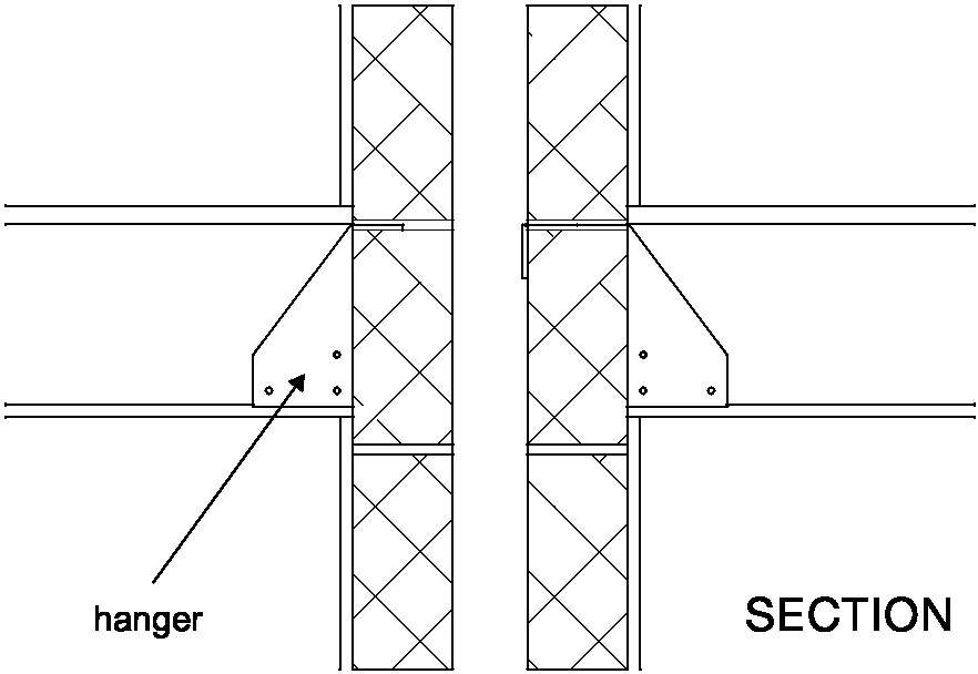
2.84 If the floor joists are to be supported on the separating wall then they should be supported on hangers and should not be built in. See Diagram 2-23.
Diagram 2-23: Wall type 2 – internal timber floor

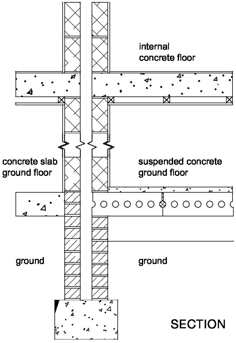
2.85 Internal concrete floors should generally be built into a type 2 separating wall and carried through to the cavity face of the leaf. The cavity should not be bridged. See Diagram 2-24.
Diagram 2-24: Wall type 2 – internal concrete floor and concrete ground floor

2.86 If the floor joists are to be supported on the separating wall then they should be supported on hangers and should not be built in.
2.87 See Building Regulation Part C - Site preparation and resistance to moisture, and Building Regulation Part L - Conservation of fuel and power.
2.88 The ground floor may be a solid slab, laid on the ground, or a suspended concrete floor. A concrete slab floor on the ground should not be continuous under a type 2 separating wall. See Diagram 2-24.
2.89 A suspended concrete floor should not be continuous under a type 2 separating wall, and should be carried through to the cavity face of the leaf. The cavity should not be bridged. See Diagram 2-24.
2.90 See Building Regulation Part C - Site preparation and resistance to moisture, and Building Regulation Part L - Conservation of fuel and power.
2.91 Where a type 2 separating wall is used it should be continuous to the underside of the roof.
2.92 The junction between the separating wall and the roof should be filled with a flexible closer which is also suitable as a fire stop. See Diagram 2-25.
Diagram 2-25: Wall type 2 – ceiling and roof junction

Resistance to the passage of sound 28