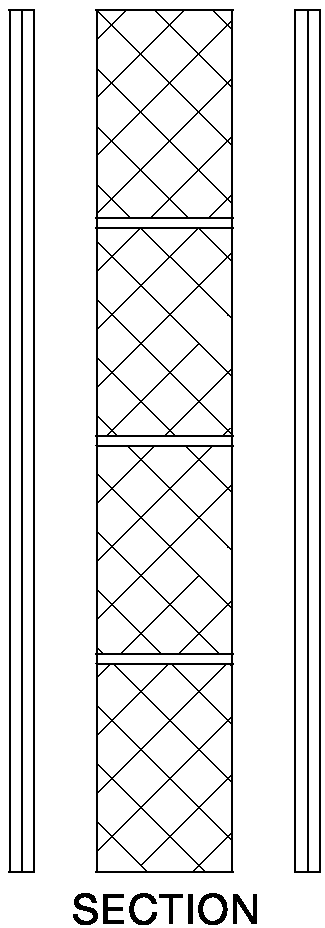
2.93 Where the roof or loft space is not a habitable room and there is a ceiling with a minimum mass per unit area of 10 kg/m2 with sealed joints, then the mass per unit area of the separating wall above the ceiling may be reduced to 150 kg/m2, but it should still be a cavity wall. See Diagram 2-25.
2.94 If lightweight aggregate blocks of density less than 1200 kg/m3 are used above ceiling level, then one side should be sealed with cement paint or plaster skim.
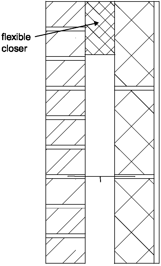
2.95 Where there is an external cavity wall, the cavity should be closed at eaves level with a suitable flexible material (e.g. mineral wool). See Diagram 2-26.
Note: A rigid connection between the inner and external wall leaves should be avoided. If a rigid material is used, then it should only be rigidly bonded to one leaf.
Diagram 2-26: External cavity wall at eaves level

2.96 There are important details in Section 3 concerning junctions between wall type 2 and separating floors.
2.97 The resistance to airborne sound depends partly on the type and mass per unit area of the core, and partly on the isolation and mass per unit area of the independent panels.
Note: Wall type 3 can give high resistance to the transmission of both airborne sound and impact sound on the wall.
2.98 Three wall type 3 constructions (types 3.1, 3.2 and 3.3) are described in this guidance.
2.99 The construction consists of either a solid or cavity masonry core wall with independent panels on both sides. These panels and any frame should not be in contact with the core wall.
2.100 Details of how junctions should be made to limit flanking transmission are also described in this guidance.
2.101 Points to watch
Do
Do not
Resistance to the passage of sound 29
2.102 The wall ties used to connect the leaves of a cavity masonry core should be tie type A. Cavity widths in separating cavity masonry cores
2.103 Recommended cavity widths are minimum values.
2.104 Independent panels.
These panels should meet the following specification:
2.105 Wall type 3.1 Solid masonry core (dense aggregate concrete block), independent panels on both room faces (see Diagrams 2-27 and 2- 28)
The required mass per unit area would be achieved by using
This is an example only. See Annex A for a simplified method of calculating mass per unit area. Alternatively use manufacturer’s actual figures where these are available.
Diagram 2-27: Wall type 3.1 with independent composite panels

Diagram 2-28: Wall type 3.1 with independent plasterboard panels

Resistance to the passage of sound 30