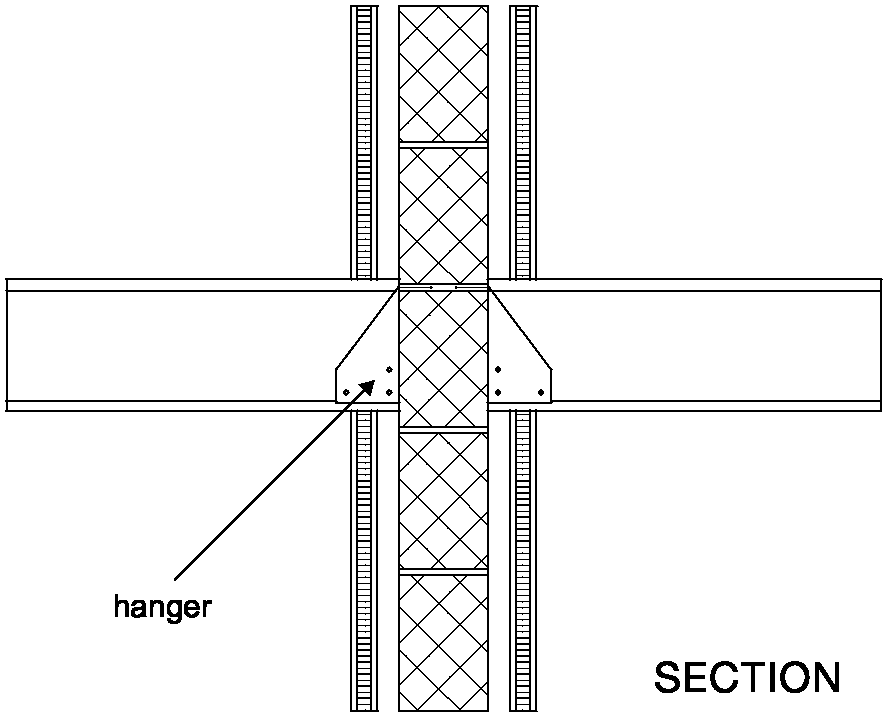
Wall types 3.1 and 3.2 (solid masonry core)
2.121 An internal concrete floor slab may only be carried through a solid masonry core if the floor base has a mass per unit area of at least 365 kg /m2. See Diagram 2-34.
Wall type 3.3 (cavity masonry core)
2.122 Internal concrete floors should generally be built into a cavity masonry core and carried through to the cavity face of the leaf. The cavity should not be bridged.
Diagram 2-33: Wall type 3 – internal timber floor

Diagram 2-34: Wall types 3.1 and 3.2 – internal concrete floor
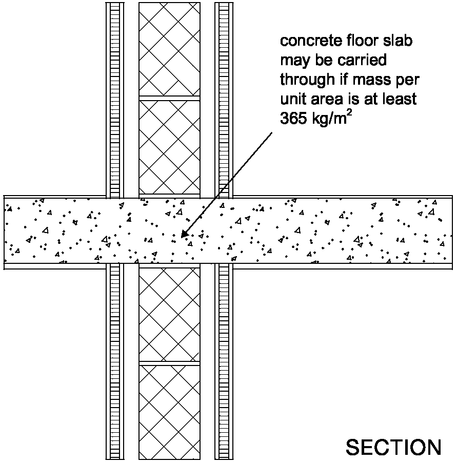 concrete floor slab may be carried through if mass per unit area is at least 365 kg/m2
2.123 If the floor joists are to be supported on the separating wall then they should be supported on hangers and should not be built in.
2.124 Spaces between the floor joists should be sealed with full depth timber blocking.
2.125 See Building Regulation Part C - Site preparation and resistance to moisture, and Building Regulation Part L - Conservation of fuel and power.
2.126 The ground floor may be a solid slab, laid on the ground, or a suspended concrete floor.
Wall type 3.1 and 3.2 (solid masonry core)
2.127 A concrete slab floor on the ground may be continuous under the solid masonry core of a type 3.1 or 3.2 separating wall.
2.128 A suspended concrete floor may only pass under the solid masonry core of a type 3.1 or 3.2 separating wall if the floor has a mass per unit area of at least 365 kg/m2.
2.129 Hollow core concrete plank and concrete beams with infilling block floors should not be continuous under the solid masonry core of a type 3.1 or 3.2 separating wall.
Wall type 3.3 (cavity masonry core)
2.130 A concrete slab floor on the ground should not be continuous under the cavity masonry core of a type 3.3 separating wall.
2.131 A suspended concrete floor should not be continuous under the cavity masonry core of a type 3.3 separating wall and should be carried through to the cavity face of the leaf. The cavity should not be bridged.
2.132 See Building Regulation Part C - Site preparation and resistance to moisture, and Building Regulation Part L - Conservation of fuel and power.
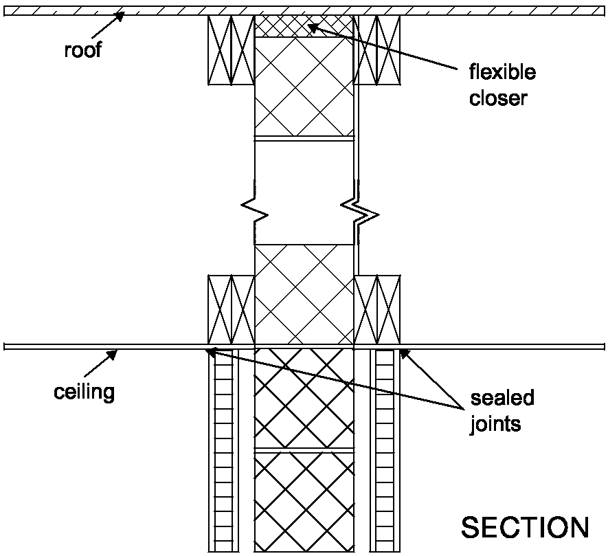
2.133 The masonry core should be continuous to the underside of the roof.
2.134 The junction between the separating wall and the roof should be filled with a flexible closer which is also suitable as a fire stop. See Diagram 2-35.
2.135 The junction between the ceiling and independent panels should be sealed with tape or caulked with sealant.
Resistance to the passage of sound 33
Diagram 2-35: Wall types 3.1 and 3.2 – ceiling and roof junction
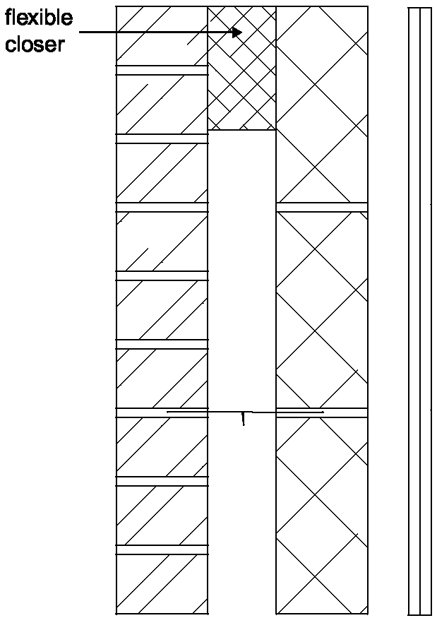
2.136 Where there is an external cavity wall, the cavity should be closed at eaves level with a suitable flexible material (e.g. mineral wool). See Diagram 2-36.
Note: A rigid connection between the inner and external wall leaves should be avoided. If a rigid material is used, then it should only be rigidly bonded to one leaf. Wall types 3.1 and 3.2 (solid masonry core)
2.137 Where the roof or loft space is not a habitable room and there is a ceiling with a minimum mass per unit area 10 kg /m2 and with sealed joints, the independent panels may be omitted in the roof space and the mass per unit area of the separating wall above the ceiling may be a minimum of 150 kg/m2. See Diagram 2-35.
2.138 If lightweight aggregate blocks of density less than 1200 kg /m3 are used above ceiling level, then one side should be sealed with cement paint or plaster skim.
Wall type 3.3 (cavity masonry core)
2.139 Where the roof or loft space is not a habitable room and there is a ceiling with a minimum mass per unit area 10 kg /m2 and with sealed joints, the independent panels may be omitted in the roof space but the cavity masonry core should be maintained to the underside of the roof.
Diagram 2-36: External cavity wall at eaves level
2.140 There are important details in Section 3 concerning junctions between wall type 3 and separating floors.
Resistance to the passage of sound 34
2.141 In this guidance only a timber framed wall is described. For steel framed walls, seek advice from the manufacturer.
2.142 The resistance to airborne sound depends on the mass per unit area of the leaves, the isolation of the frames, and the absorption in the cavity between the frames.
2.143 The construction consists of timber frames, with plasterboard linings on room surfaces and with absorbent material between the frames.
2.144 One wall type 4 construction (type 4.1) is described in this guidance.
2.145 Details of how junctions should be made to limit flanking transmission are also described in this guidance.
2.146 Points to watch
Do
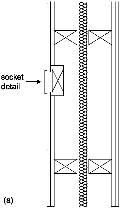
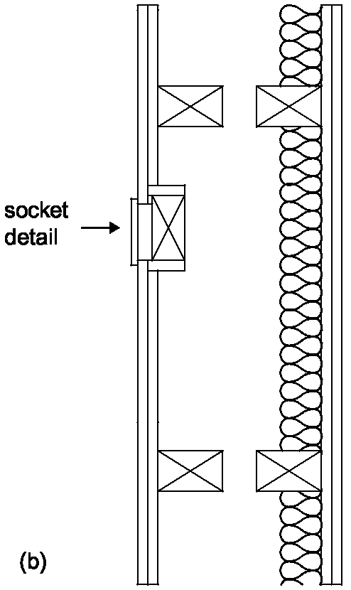
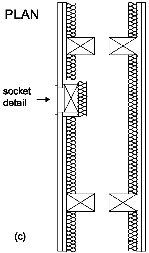
2.147 Wall type 4.1 Double leaf frames with absorbent material (see Diagram 2-37)
Note: A masonry core may be used where required for structural purposes, but the core should be connected to only one frame.
Do not
Resistance to the passage of sound 35
Diagram 2-37: Wall type 4.1 Junction requirements for wall type 4
2.148 No guidance available (seek specialist advice).
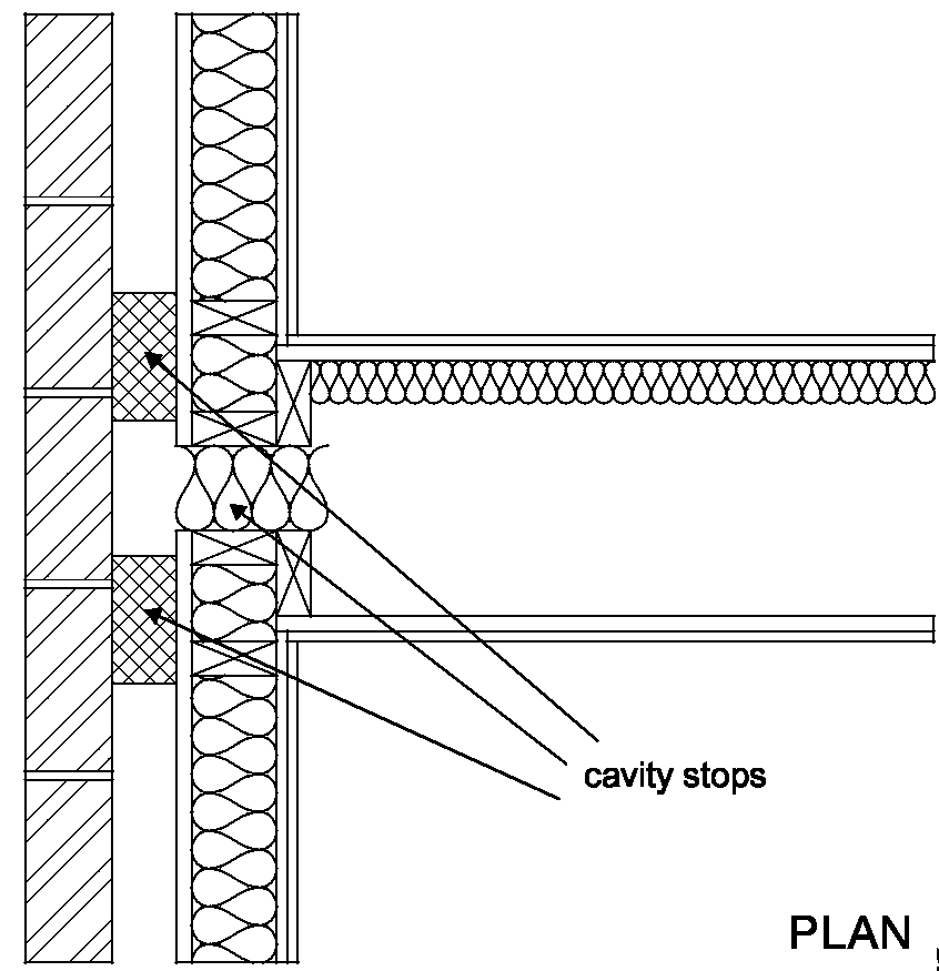
2.149 Where the external wall is a cavity wall:
2.150 The wall finish of the inner leaf of the external wall should be:
Diagram 2-38: Wall type 4 – external cavity wall with timber frame inner leaf
Junctions with an external solid masonry wall
2.151 No guidance available (seek specialist advice).
Resistance to the passage of sound 36