

Junctions with internal framed walls
2.152 There are no restrictions on internal walls meeting a type 4 separating wall.
2.153 There are no restrictions on internal framed walls meeting a type 4 separating wall.
2.154 Block the air paths through the wall into the cavity by using solid timber blockings or continuous ring beam or joists.
Junctions with internal concrete floors
2.155 No guidance available (seek specialist advice).
Junctions with timber ground floors
2.156 Block the air paths through the wall into the cavity by using solid timber blockings or a continuous ring beam or joists.
2.157 See Building Regulation Part C - Site preparation and resistance to moisture, and Building Regulation Part L - Conservation of fuel and power.
Junctions with concrete ground floors
2.158 The ground floor may be a solid slab, laid on the ground, or a suspended concrete floor. A concrete slab floor on the ground may be continuous under a type 4 separating wall. A suspended concrete floor may only pass under a wall type 4 if the floor has a mass per unit area of at least 365 kg /m2.
2.159 See Building Regulation Part C - Site preparation and resistance to moisture, and Building Regulation Part L - Conservation of fuel and power.
Junctions with ceiling and roof space
2.160 The wall should preferably be continuous to the underside of the roof.
2.161 The junction between the separating wall and the roof should be filled with a flexible closer.
2.162 The junction between the ceiling and the wall linings should be sealed with tape or caulked with sealant.
Where the roof or loft space is not a habitable room and there is a ceiling with a minimum mass per unit area 10 kg/m2 and with sealed joints, either:
2.163 Where there is an external wall cavity, the cavity should be closed at eaves level with a suitable material.
Junctions with separating floors
2.164 There are important details in Section 3 concerning junctions between wall type 4 and separating floors.
Resistance to the passage of sound 37
3.1 This Section gives examples of floor types which, if built correctly, should achieve the performance standards set out in Section 0: Performance - Table 1 a.
3.2 The guidance in this section is not exhaustive and other designs, materials or products may be used to achieve the performance standards set out in Section 0: Performance - Table 1a. Advice should be sought from the manufacturer or other appropriate source.
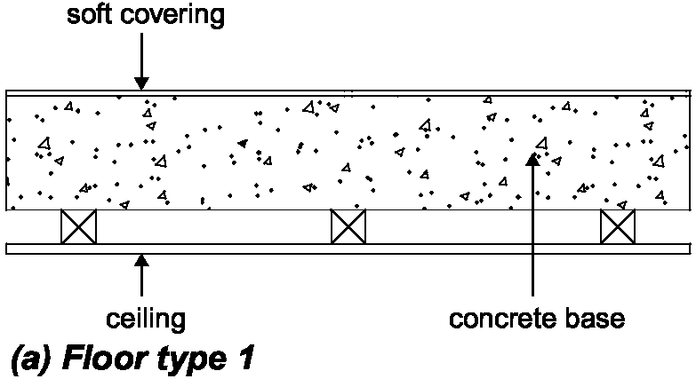
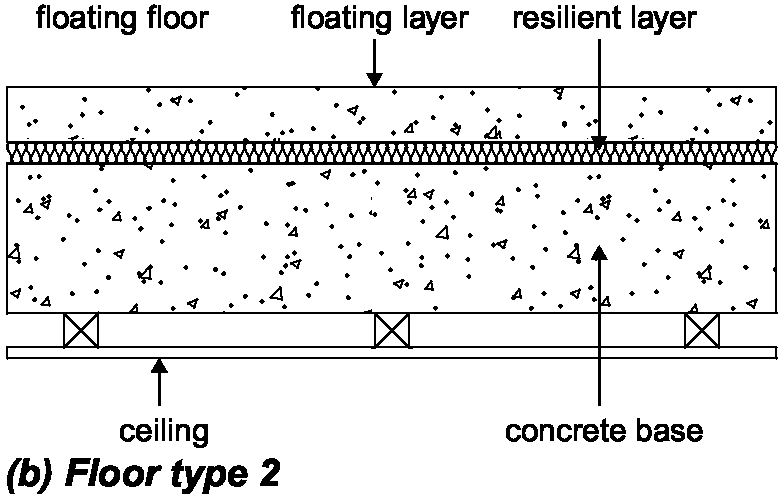
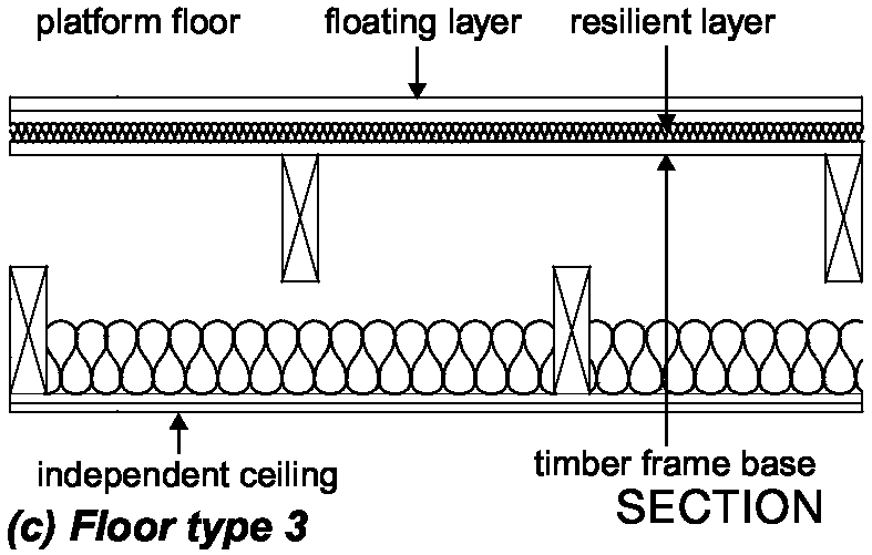
3.3 The floors are grouped into three main types. See Diagram 3-1.
3.4 Floor type 1: Concrete base with ceiling and soft floor covering
The resistance to airborne sound depends mainly on the mass per unit area of the concrete base and partly on the mass per unit area of the ceiling. The soft floor covering reduces impact sound at source.
3.5 Floor type 2: Concrete base with ceiling and floating floor
The resistance to airborne and impact sound depends on the mass per unit area of the concrete base, as well as the mass per unit area and isolation of the floating layer and the ceiling. The floating floor reduces impact sound at source.
3.6 Floor type 2: Floating floor
Floor type 2 requires one of the floating floors described in this section. The description of floor type 2 contains a suffix (a), (b) or (c) which refers to the floating floor used.
3.7 Floor type 3: Timber frame base with ceiling and platform floor
The resistance to airborne and impact sound depends on the structural floor base and the isolation of the platform floor and the ceiling. The platform floor reduces impact sound at source.
3.8 Ceiling treatment
Each floor type requires one of the ceiling treatments described in this section. The description of each floor type contains a suffix A, B or C that refers to the ceiling treatment used.
3.9 Within each floor type the constructions are ranked, as far as possible, with constructions providing better sound insulation given first.
Junctions between separating floors and other building elements
3.10 In order for the floor construction to be fully effective, care should be taken to correctly detail the junctions between the separating floor and other elements such as external walls, separating walls and floor penetrations. Recommendations are also given for the construction of these other elements where it is necessary to control flanking transmission. Notes and diagrams explain the junction details for each of the separating floor types.
Diagram 3-1: Types of separating floor


3.11 Table 3.1 indicates the inclusion of guidance in this document on the junctions that may occur between each of the separating floor types and various attached building elements.
Resistance to the passage of sound 38
Table 3.1 Separating floor junctions reference table.
Separating wall type
| Building element attached to separating floor | Type 1 | Type 2 | Type 3 | |
| External cavity wall with masonry inner leaf | G | G | G | |
| External cavity wall with timber frame inner leaf | G | G | G | |
| External solid masonry wall | N | N | N | |
| Internal wall - framed | G | G | G | |
| Internal wall - masonry | G | G | N | |
| Floor penetrations | G | G | G | |
| For flats the following may also apply: | ||||
| Separating wall type 1 - solid masonry | G | G | G | |
| Separating wall type 2 - cavity masonry | G | G | G | |
| Separating wall type 3 - masonry between independent panels | G | G | G | |
| Separating wall type 4 – framed wall with absorbent material | N | N | G |
Key: G = guidance available; N = no guidance available (seek specialist advice)
Note:
Where any building element functions as a separating element (e.g. a ground floor that is also a separating floor for a basement flat) then the separating element requirements should take precedence.
Beam and block floors
3.12 For beam and block separating floors, seek advice from the manufacturer.
Mass per unit area of floors
3.13 The mass per unit area of a floor is expressed in kilograms per square metre (kg/m2). The mass per unit area of floors should be obtained from manufacturer’s data or calculated using the method shown in Annex A.
3.14 The density of the materials used (and on which the mass per unit area of the floor depends) is expressed in kilograms per cubic metre (kg /m3).
3.15 Where appropriate, the mass per unit area of a bonded screed may be included in the calculation of the mass per unit area of the floor.
3.16 The mass per unit area of a floating screed should not be included in the calculation of the mass per unit area of the floor.
Ceiling treatments
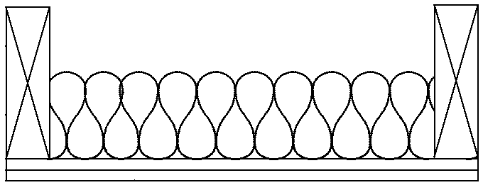
3.17 Each floor type should use one of the following three ceiling treatments (A, B or C). See Diagram 3-2.
3.18 The ceiling treatments are ranked, in order of sound insulation performance from A to C, with constructions providing higher sound insulation given first.
Note: Use of a better performing ceiling than that described in the guidance should improve the sound insulation of the floor provided there is no significant flanking transmission.
3.19 Ceiling treatment A, independent ceiling with absorbent material
Ceiling treatment A should meet the following specification:
The ceiling should be supported by one of the following methods:
Resistance to the passage of sound 39
3.20 Points to watch
Do
Do seal the perimeter of the independent ceiling with tape or sealant.
Do not
Do not create a rigid or direct connection between the independent ceiling and the floor base.
3.21 Ceiling treatment B, plasterboard on proprietary resilient bars with absorbent material
Ceiling treatment B should meet the following specification:
single layer of plasterboard, minimum mass per unit area of plasterboard 10 kg /m2
fixed using proprietary resilient metal bars. On concrete floors, these resilient metal bars should be fixed to timber battens. For fixing details, seek advice from the manufacturer.
an absorbent layer of mineral wool (minimum density 10 kg/m3) that fills the ceiling void.
3.22 Ceiling treatment C, plasterboard on timber battens or proprietary resilient channels with absorbent material
Ceiling treatment C should meet the following specification:
single layer of plasterboard, minimum mass per unit area 10 kg/m2
fixed using timber battens or proprietary resilient channels
if resilient channels are used, incorporate an absorbent layer of mineral wool (minimum density 10 kg/m3) that fills the ceiling void.
Diagram 3-2: Ceiling treatments A , B and C
Note: Electrical cables give off heat when in use and special precautions may be required when they are covered by thermally insulating materials. See BRE BR 262, Thermal Insulation: avoiding risks, section 2.3. Installing recessed light fittings in ceiling treatments A to C can reduce their resistance to the passage of airborne and impact sound.
Floor type 1: Concrete base with ceiling and soft floor covering
3.23 The resistance to airborne sound depends mainly on the mass per unit area of the concrete base and partly on the mass per unit area of the ceiling. The soft floor covering reduces impact sound at source.
Constructions
3.24 The construction consists of a concrete floor base with a soft floor covering and a ceiling.
3.25 Two floor type 1 constructions (types 1.1C and 1.2B) are described in this guidance which should be combined with the appropriate ceiling and soft floor covering.
3.26 Details of how junctions should be made to limit flanking transmission are also described in this guidance.

Ceiling treatment A (independent joists)

Ceiling treatment B (resilient bars)

Ceiling treatment C (timber battens)

Ceiling treatment C (resilient channels)
Resistance to the passage of sound 40