3.27 Points to watch
Do
Do not
3.28 Soft floor covering
The soft floor covering should meet the following specification:
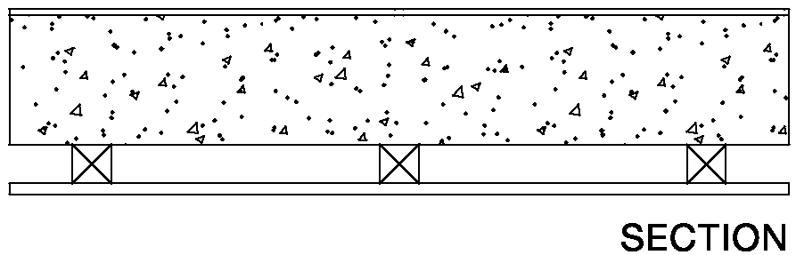
3.29 Floor type 1.1C Solid concrete slab (cast in-situ or with permanent shuttering), soft floor covering, ceiling treatment C (see Diagram 3-3)
Diagram 3-3: Floor type 1.1 C
Floor type 1.1 with ceiling treatment C
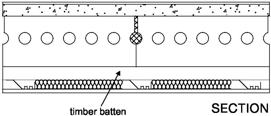
3.30 Floor Type 1.2B Concrete planks (solid or hollow), soft floor covering, ceiling treatment B (see Diagram 3-4)
Diagram 3-4: Floor type 1.2B
Floor type 1.2 with ceiling treatment B
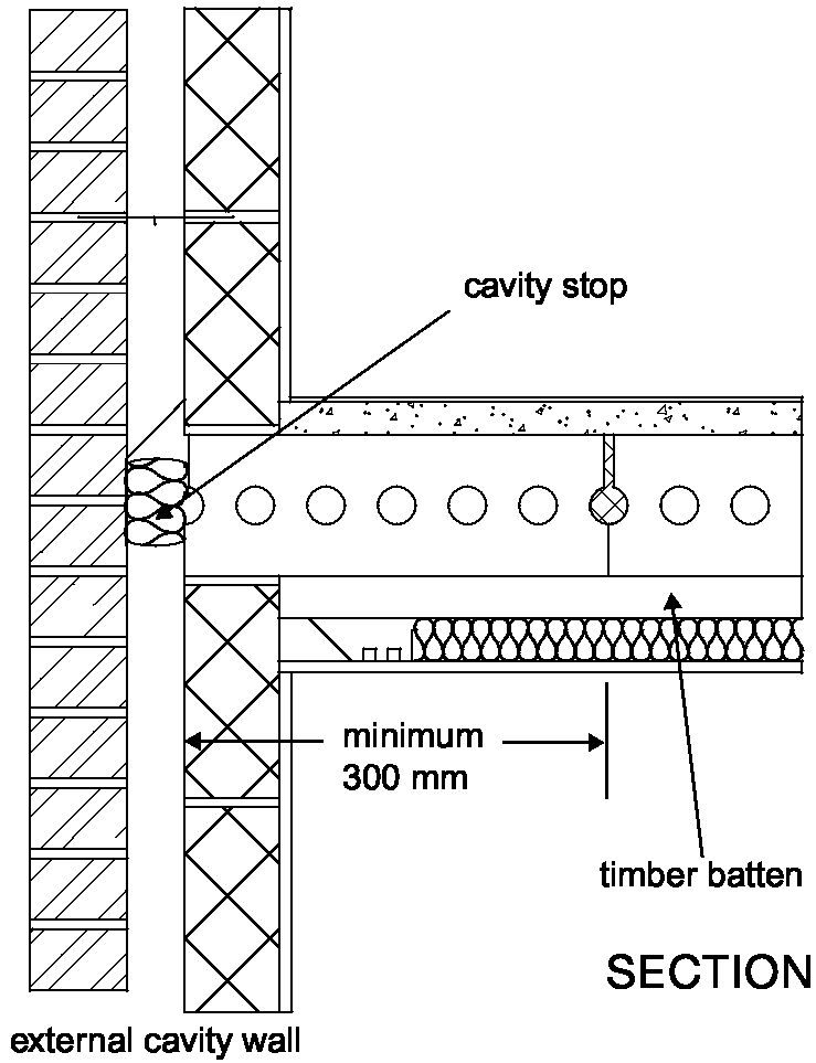
3.31 Where the external wall is a cavity wall:
3.32 The masonry inner leaf of an external cavity wall should have a mass per unit area of at least 120 kg/m2 excluding finish.
Resistance to the passage of sound 41
3.33 The floor base (excluding any screed) should be built into a cavity masonry external wall and carried through to the cavity face of the inner leaf. The cavity should not be bridged.
Floor type 1.2B
3.34 Where floor type 1.2B is used and the planks are parallel to the external wall the first joint should be a minimum of 300 mm from the cavity face of the inner leaf. See Diagram 3-5.
3.35 See details in Section 2 concerning the use of wall ties in external masonry cavity walls.

Junctions with an external cavity wall with timber frame inner leaf
3.36 Where the external wall is a cavity wall: the outer leaf of the wall may be of any construction, and
the cavity should be stopped with a flexible closer.
the wall finish of the inner leaf of the external wall should be two layers of plasterboard, each sheet of plasterboard to be of minimum mass per unit area 10 kg/m2, and all joints should be sealed with tape or caulked with sealant.
Junctions with an external solid masonry wall
3.37 No guidance available (seek specialist advice).
Junctions with internal framed walls
3.38 There are no restrictions on internal framed walls meeting a type 1 separating floor. Junctions with internal masonry walls
3.39 The floor base should be continuous through, or above an internal masonry wall.
3.40 The mass per unit area of any load bearing internal wall or any internal wall rigidly connected to a separating floor should be at least 120 kg/m2 excluding finish.
Junctions with floor penetrations (excluding gas pipes)
3.41 Pipes and ducts that penetrate a floor separating habitable rooms in different flats should be enclosed for their full height in each flat. See Diagram 3-6.
3.42 The enclosure should be constructed of material having a mass per unit area of at least 15 kg/m2. Either line the enclosure, or wrap the duct or pipe within the enclosure, with 25 mm unfaced mineral fibre.
3.43 Penetrations through a separating floor by ducts and pipes should have fire protection to satisfy Building Regulation Part B - Fire safety. Fire stopping should be flexible and prevent rigid contact between the pipe and floor.
Diagram 3-6: Floor type 1 floor penetrations
Note: There are requirements for ventilation of ducts at each floor where they contain gas pipes. Gas pipes may be contained in a separate ventilated duct or they can remain unenclosed. Where a gas service is installed, it shall comply with relevant codes and standards to ensure safe and satisfactory operation. See The Gas Safety (Installation and Use) Regulations 1998, SI 1998 No.2451.
Resistance to the passage of sound Approved Document E 42
SEPARATING FLOORS (NEW BUILDINGS) SOUNDPROOFING
For flats where there are separating walls the following may also apply:
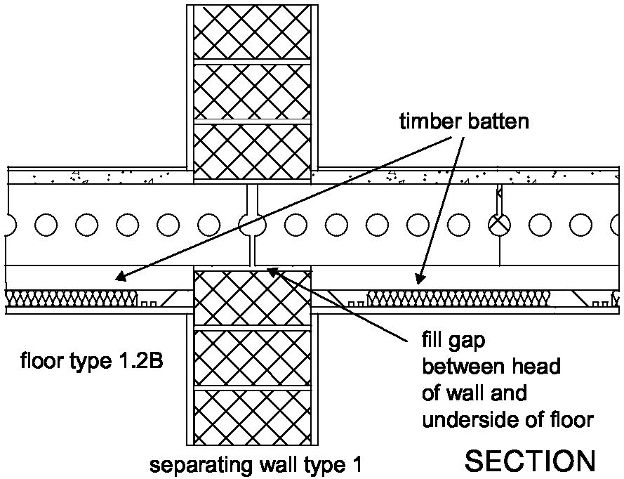
Junctions with separating wall type 1 - solid masonry Floor type 1.1 C
Diagram 3-7: Floor type 1.1C wall type 1
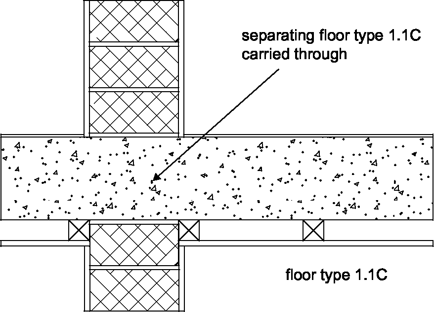
3.44 A separating floor type 1.1C base (excluding any screed) should pass through a separating wall type 1. See Diagram 3-7.
Floor type 1.2B
Diagram 3-8: Floor type 1.2B wall type 1
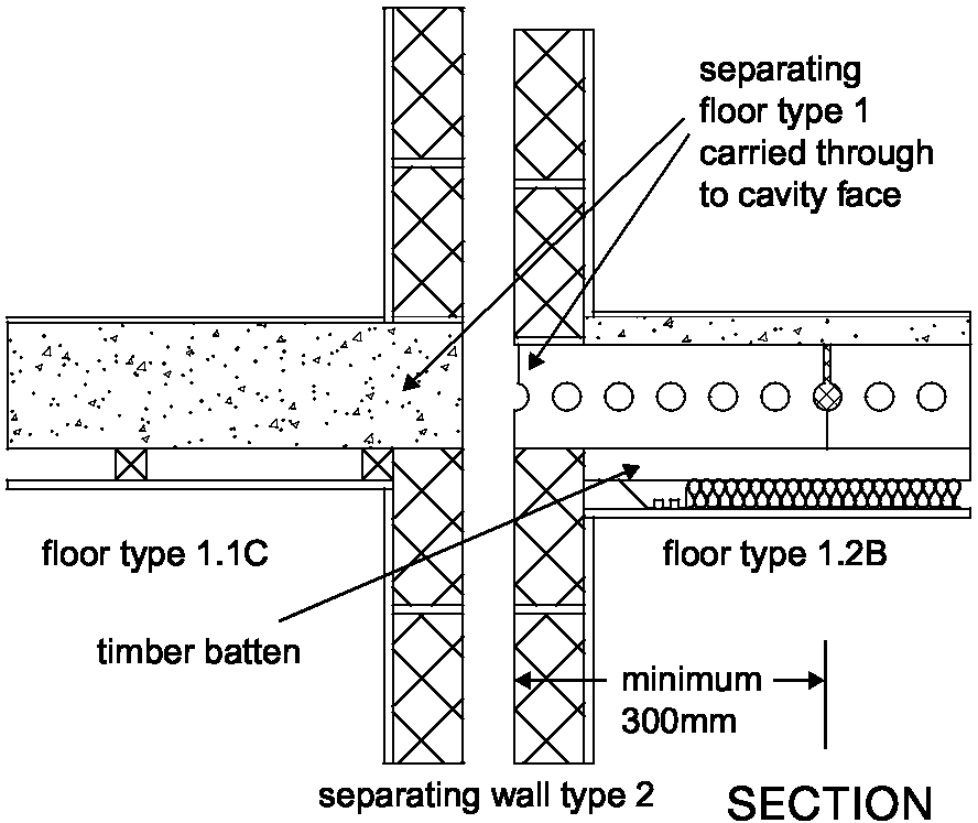
Junctions with separating wall type 2 - cavity masonry
3.46 The mass per unit area of any leaf that is supporting or adjoining the floor should be at least 120 kg/m2 excluding finish.
3.47 The floor base (excluding any screed) should be carried through to the cavity face of the leaf. The wall cavity should not be bridged. See Diagram 3-9. Floor type 1.2B
3.48 Where floor type 1.2B is used and the planks are parallel to the separating wall the first joint should be a minimum of 300 mm from the inner face of the adjacent cavity leaf. See Diagram 3-9. Diagram 3-9: Floor types 1.1 C and 1.2B wall type 2
Junctions with separating wall type 3 - masonry between independent panels
Junctions with separating wall type 3.1 and 3.2 (solid masonry core)
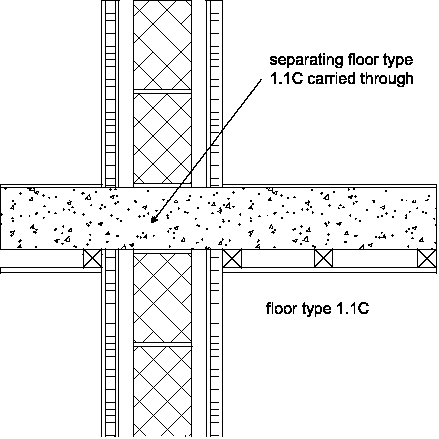
Floor type 1.1 C
3.49 A separating floor type 1.1C base (excluding any screed) should pass through separating wall types 3.1 and 3.2. See Diagram 3-10.
separating wall type 1
 SECTION
Picture
separating floor type 1.1 C carried through
Picture
SECTION
Picture
separating floor type 1.1 C carried through
Picture
fill gap
between head of wall and underside of floor Picture
separating floor type 1 carried through to cavity face
3.45 A separating floor type 1.2B base (excluding any screed) should not be continuous through a separating wall type 1. See Diagram 3-8.
Resistance to the passage of sound 43
Diagram 3-10: Floor type 1.1 C wall types 3.1 and 3.2
Floor type 1.2B
3.50 A separating floor type 1.2B base (excluding any screed) should not be continuous through a separating wall type 3.
3.51 Where separating wall type 3.2 is used with floor type 1.2B and the planks are parallel to the separating wall the first joint should be a minimum of 300 mm from the centreline of the masonry core. Junctions with separating wall type 3.3 (cavity masonry core)
3.52 The mass per unit area of any leaf that is supporting or adjoining the floor should be at least 120 kg/m2 excluding finish.
3.53 The floor base (excluding any screed) should be carried through to the cavity face of the leaf of the core. The cavity should not be bridged.
Floor type 1.2B
3.54 Where floor type 1.2B is used and the planks are parallel to the separating wall the first joint should be a minimum of 300 mm from the inner face of the adjacent cavity leaf of the masonry core. Junctions with separating wall type 4 - timber frames with absorbent material
3.55 No guidance available (seek specialist advice).
Floor type 2: Concrete base with ceiling and floating floor
3.56 The resistance to airborne and impact sound depends on the mass per unit area of the concrete base, as well as the mass per unit area and isolation of the floating layer and the ceiling. The floating floor reduces impact sound at source.
Constructions
3.57 The construction consists of a concrete floor base with a floating floor and a ceiling. The floating floor consists of a floating layer and a resilient layer.
3.58 Two floor type 2 constructions (types 2.1C and 2.2B) are described in this guidance, which should be combined with the appropriate ceiling and any one of the three floating floor options (a), (b) or (c).
3.59 Details of how junctions should be made to limit flanking transmission are also described in this guidance.
Limitations
3.60 Where resistance to airborne sound only is required the full construction should still be used.
3.61 Points to watch
Do
Do not
separating wall types 3.1 and 3.2
separating floor type 1.1 C carried through
Resistance to the passage of sound 44