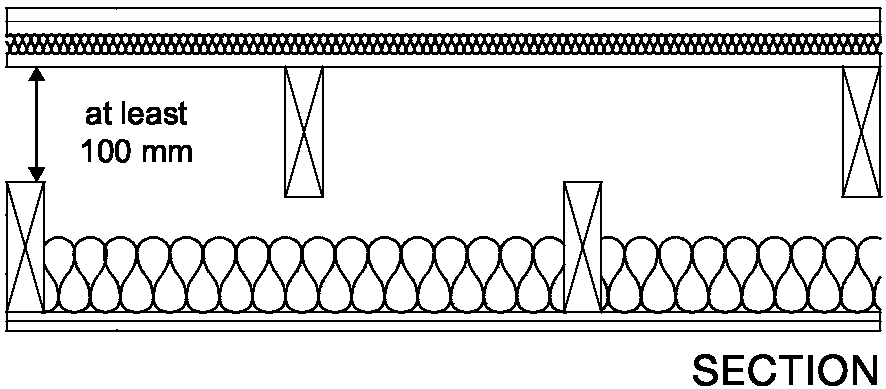
3.90 The mass per unit area of any leaf that is supporting or adjoining the floor should be at least 120 kg/m2 excluding finish.
3.91 The floor base (excluding any screed) should be carried through to the cavity face of the leaf of the core. The cavity should not be bridged.
Floor type 2.2B
3.92 Where floor type 2.2B is used and the planks are parallel to the separating wall the first joint should be a minimum of 300 mm from the inner face of the adjacent cavity leaf of the masonry core.
Junctions with separating wall type 4 - timber frames with absorbent material
3.93 No guidance available (seek specialist advice).
Floor type 3: Timber frame base with ceiling and platform floor
3.94 The resistance to airborne and impact sound depends on the structural floor base and the isolation of the platform floor and the ceiling. The platform floor reduces impact sound at source.
Construction
3.95 The construction consists of a timber frame structural floor base with a deck, platform floor and ceiling treatment A. The platform floor consists of a floating layer and a resilient layer.
3.96 One floor type 3 construction (type 3.1A) is described in this guidance.
3.97 Details of how junctions should be made to limit flanking transmission are also described in this guidance.
Limitations
3.98 Where resistance to airborne sound only is required the full construction should still be used.
3.99 Points to watch
Do
Platform floor
Do not
3.100 Floor type 3.1A Timber frame base with ceiling treatment A and platform floor (see Diagram 3-20)
Diagram 3-20: Floor type 3.1A

Resistance to the passage of sound 49
3.101 Platform floor
The floating layer should be:
The floating layer should be laid loose on a resilient layer.
Example 1
Example 2
3.102 Resilient layer
The resilient layer specification is:
Note: The lower figure of density for the resilient layer gives a higher resistance to impact sound but a ‘softer’ floor. In such cases additional support can be provided around the perimeter of the floor by using a timber batten with a foam strip along the top attached to the wall.
3.103 Where the external wall is a cavity wall:
3.104 The masonry inner leaf of a cavity wall should be lined with an independent panel as described for wall type 3.
3.105 The ceiling should be taken through to the masonry. The junction between the ceiling and the independent panel should be sealed with tape or caulked with sealant.
3.106 Use any normal method of connecting floor base to wall but block air paths between floor and wall cavities.
3.107 Where the mass per unit area of the inner leaf is greater than 375 kg /m2 the independent panels are not required.
3.108 See details in Section 2 concerning the use of wall ties in external masonry cavity walls.
3.109 Where the external wall is a cavity wall:
3.110 The wall finish of the inner leaf of the external wall should be:
3.111 Use any normal method of connecting floor base to wall. Where the joists are at right angles to the wall, spaces between the floor joists should be sealed with full depth timber blocking.
3.112 The junction between the ceiling and wall lining should be sealed with tape or caulked with sealant.
3.113 No guidance available (seek specialist advice).
3.114 Where the joists are at right angles to the wall, spaces between the floor joists should be sealed with full depth timber blocking.
3.115 The junction between the ceiling and the internal framed wall should be sealed with tape or caulked with sealant.
3.116 No guidance available (seek specialist advice).
Resistance to the passage of sound 50
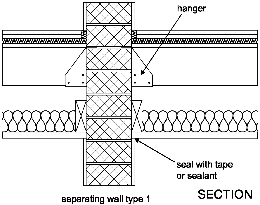
3.117 Pipes and ducts that penetrate a floor separating habitable rooms in different flats should be enclosed for their full height in each flat. See Diagram 3-21.
3.118 The enclosure should be constructed of material having a mass per unit area of at least 15 kg/m2. Either line the enclosure, or wrap the duct or pipe within the enclosure, with 25 mm unfaced mineral wool.
3.119 Leave a small gap (approx. 5 mm) between enclosure and floating layer and seal with sealant or neoprene. The enclosure may go down to the floor base, but ensure that the enclosure is isolated from the floating layer.
3.120 Penetrations through a separating floor by ducts and pipes should have fire protection to satisfy Building Regulation Part B - Fire safety. Fire stopping should be flexible and also prevent rigid contact between the pipe and floor.
Note: There are requirements for ventilation of ducts at each floor where they contain gas pipes. Gas pipes may be contained in a separate ventilated duct or they can remain unenclosed. Where a gas service is installed, it shall comply with relevant codes and standards to ensure safe and satisfactory operation. See The Gas Safety (Installation and Use) Regulations 1998, SI 1998 No.2451.
Diagram 3-21: Floor type 3 – floor penetrations
For flats where there are separating walls the following may also apply:
Junctions with a separating wall type 1 - solid masonry
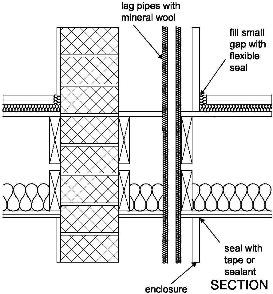
3.121 If floor joists are to be supported on the separating wall then they should be supported on hangers and should not be built in. See Diagram 3-22.
3.122 The junction between the ceiling and wall should be sealed with tape or caulked with sealant.
Diagram 3-22: Floor type 3 – wall type 1
Junctions with a separating wall type 2 - cavity masonry
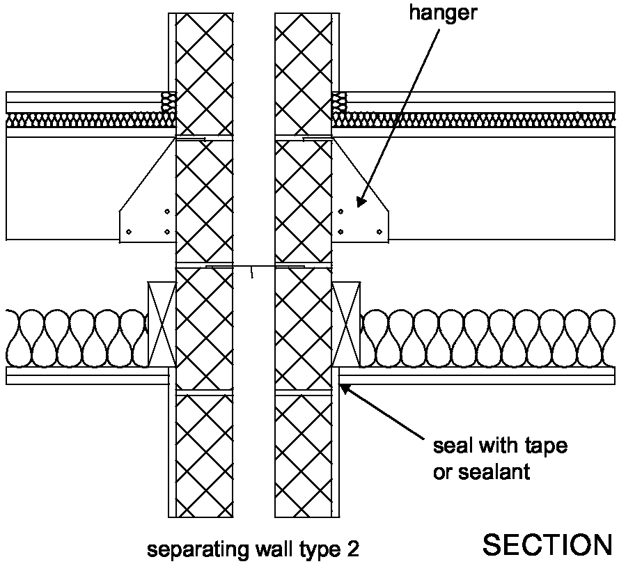
3.123 If floor joists are to be supported on the separating wall then they should be supported on hangers and should not be built in. See Diagram 3-23.
3.124 The inner leaf of a cavity wall should be lined with an independent panel as described in wall type 3.
3.125 The ceiling should be taken through to the masonry. The junction between the ceiling and the independent panel should be sealed with tape or caulked with sealant.
3.126 Where the mass per unit area of the inner leaf is greater than 375 kg /m2 the independent panels are not required.
Resistance to the passage of sound 51
Diagram 3-23: Floor type 3 – wall type 2
Junctions with a separating wall type 3 - masonry between independent panels
3.127 If floor joists are to be supported on the separating wall then they should be
supported on hangers and should not be built in.
3.128 The ceiling should be taken through to the masonry. The junction between the ceiling and the independent panel should be sealed with tape or caulked with sealant.
Junctions with a separating wall type 4 - timber frames with absorbent material
3.129 Where the joists are at right angles to the wall, spaces between the floor joists should be sealed with full depth timber blocking.
3.130 The junction of the ceiling and wall lining should be sealed with tape or caulked with sealant.
Resistance to the passage of sound Approved Document E 52
Section 4: Dwelling-houses and flats formed by material change of use
Introduction
4.1 This Section gives guidance on dwelling-houses and flats formed by material change of use. For rooms for residential purposes formed by material change of use see Section 6.
4.2 It may be that an existing wall, floor or stair in a building that is to undergo a material change of use will achieve the performance standards set out in Section 0: Performance - Table 1 a without the need for remedial work. This would be the case if the construction was generally similar (including flanking constructions) to one of the constructions in Sections 2 and 3 (e.g. concerning the mass requirement, the structure under consideration should be within 15% of the mass per unit area of a construction listed in the relevant section).
4.3 In other circumstances it may be possible to use the guidance in Section 2 or 3 (including flanking constructions) to determine the appropriate remedial treatment which will result in the construction achieving the performance standards in Section 0: Performance - Table 1 a.
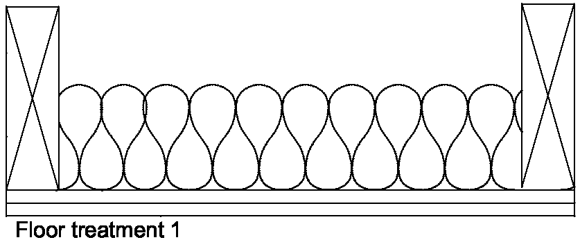
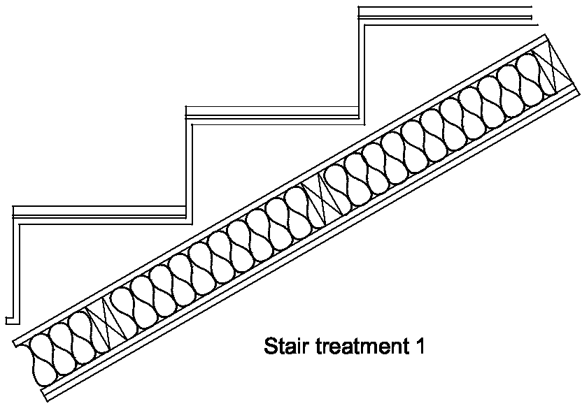
4.4 For situations where it is uncertain whether the existing construction achieves the performance standards set out in Section 0: Performance - Table 1 a, this section describes one wall treatment, two floor treatments and one stair treatment as shown in Diagram 4-1. These constructions can be used to increase the sound insulation.
4.5 The guidance in this section is not exhaustive and other designs, materials or products may be used to achieve the performance standards set out in Section 0: Performance - Table 1 a. Advice should be sought from the manufacturer or other appropriate source.
4.6 Wall treatment 1 Independent panel(s) with absorbent material
The resistance to airborne sound depends on the form of existing construction, the mass of the independent panel(s), the isolation of the panel(s) and the absorbent material.
4.7 Floor treatment 1 Independent ceiling with absorbent material
The resistance to airborne and impact sound depends on the combined mass of the existing floor and the independent ceiling, the absorbent material, the isolation of the independent ceiling and the airtightness of the whole construction.
4.8 Floor treatment 2 Platform floor with absorbent material
The resistance to airborne and impact sound depends on the total mass of the floor, the effectiveness of the resilient layer and the absorbent material.
4.9 Stair treatment 1 Stair covering and independent ceiling with absorbent material
To be used where a timber stair performs a separating function. The resistance to airborne sound depends mainly on the mass of the stair, the mass and isolation of any independent ceiling and the airtightness of any cupboard or enclosure under the stairs. The stair covering reduces impact sound at source.
4.10 In all cases it may be necessary to control flanking transmission in order to achieve the performance standards set out in Section 0: Performance - Table 1a. See Section 4: Junction requirements for material change of use.
4.11 Special attention needs to be given to situations where flanking walls or floors are continuous across separating walls or floors as a result of the conversion work. In such instances additional treatments may be required to control flanking transmission along these continuous elements. Specialist advice may be needed.
4.12 Significant differences may frequently occur between the construction and layout of each converted unit in a development. Building control bodies should have regard to the guidance in Section 1 when deciding on the application of pre-completion testing to material change of use.
4.13 For some historic buildings undergoing a material change of use, it may not be practical to improve the sound insulation to the performance standards set out in Section 0: Performance - Table 1 a. In such cases refer to Section 0: Performance, paragraph 0.7.
4.14 Wall and floor treatments will impose additional loads on the existing structure. The structure should be assessed to ensure that the additional loading can be carried safely, with appropriate strengthening applied where necessary.
4.15 Floor or wall penetrations, such as ducts or pipes, passing through separating elements in conversions can reduce the level of sound insulation. Guidance on the treatment of floor penetrations is given below.
Resistance to the passage of sound 53
4.16 Before a floor treatment is applied appropriate remedial work to the existing construction should be undertaken as described in paragraphs 4.17 and 4.18.
4.17 If the existing floor is timber then gaps in floor boarding should be sealed by overlaying with hardboard or filled with sealant.
4.18 Extensive remedial work to reduce flanking transmission may also be necessary to achieve the performance standards set out in Section 0: Performance - Table 1 a. This may involve wall linings, see Section 4: Junction requirements for material change of use, paragraphs 4.43 and 4.44.
4.19 The separating walls described in this section should be used between dwelling-houses, or flats formed by material change of use and corridors in order to control flanking transmission and to provide the required sound insulation. However, it is likely that the sound insulation will be reduced by the presence of a door.
4.20 Ensure that any door has good perimeter sealing (including the threshold where practical) and a minimum mass per unit area of 25 kg/m2 or a minimum sound reduction index of 29 dB Rw (measured according to BS EN ISO 140- 3:1995 and rated according to BS EN ISO 717- 1:1997). The door should also satisfy the Requirements of Building Regulation Part B - Fire safety.
4.21 Noisy parts of the building should preferably have a lobby, double door or high performance doorset to contain the noise. Where this is not possible, nearby flats should have similar protection. However, there should be a sufficient number of them that are suitable for disabled access, see Building Regulation Part M - Access and facilities for disabled people.
Diagram 4-1: Treatments for material change of use


Resistance to the passage of sound 54